LQR Control Algorithm
Simple learning notes on LQR
Linear Quadratic Regulator - LQR#
- Linear (linear model)
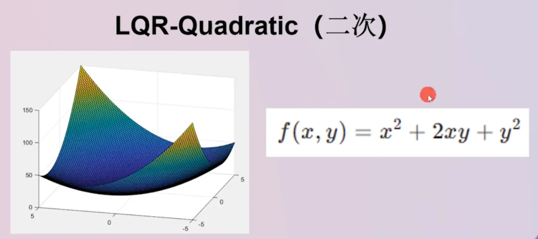
- Quadratic (quadratic): LQR uses properties of quadratic functions to find the minimum point—that is, an energy-optimal point / an energy-optimal control strategy.
- Regulator
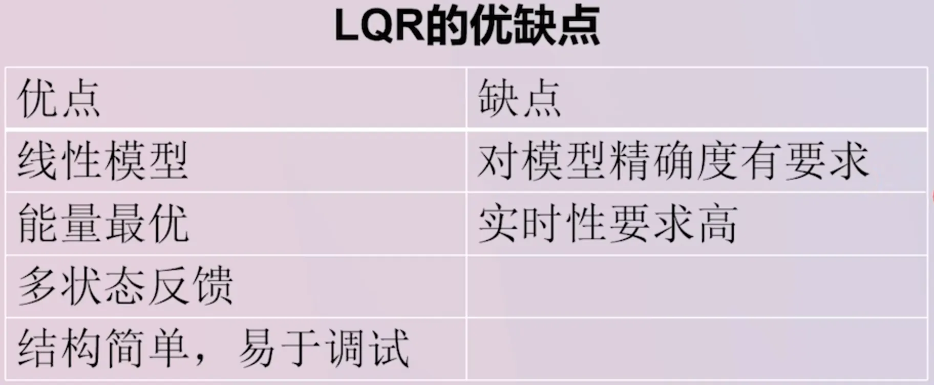
- Pros and cons (more suitable for MIMO models)
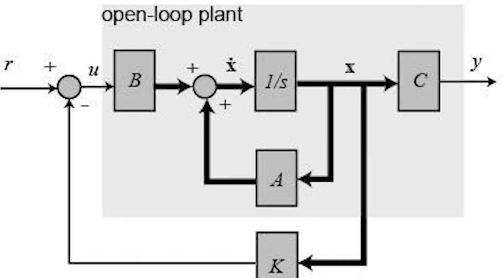
Difference from PID#
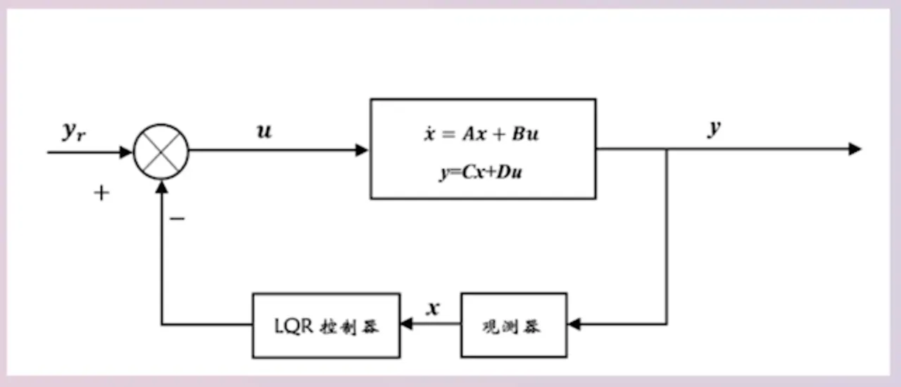
PID is output-feedback control; LQR is state-feedback control, which uses multi-dimensional control information. The figure below shows the LQR control block diagram.
Solving the gain matrix K#
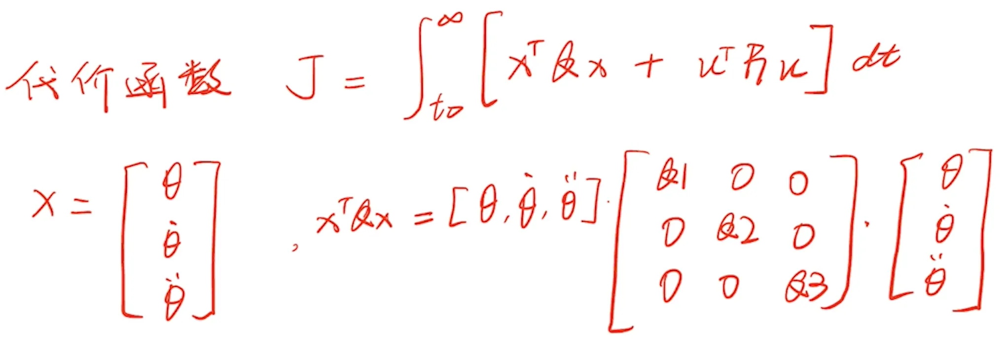
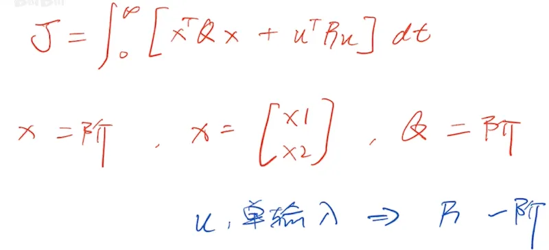
First, define a cost function , which measures whether the method is optimal. The magnitudes of , , (weights) determine the importance of each term in .
Riccati equation (Riccati): based on the cost function, the goal is to find the energy-optimal solution and thus compute the gain matrix (in MATLAB you can call the function directly).

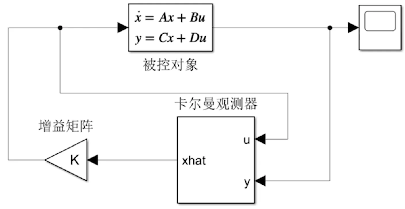
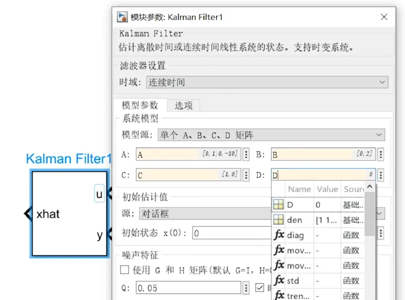
What an observer is for#
We need an observer essentially because state-feedback control requires knowing each state variable being fed back. Sometimes some state variables cannot be obtained directly from sensors.
If a state variable cannot be obtained directly from sensors, we use an observer to estimate that unknown state variable. (If we only use mathematical differentiation/integration, it can introduce lots of noise and may also cause phase lag. Some data cannot be obtained from sensors directly, nor obtained simply via differentiation/integration.)
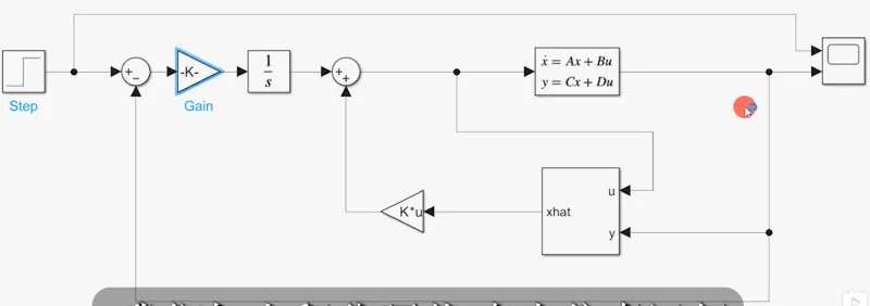
LQR Simulation#
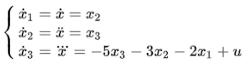
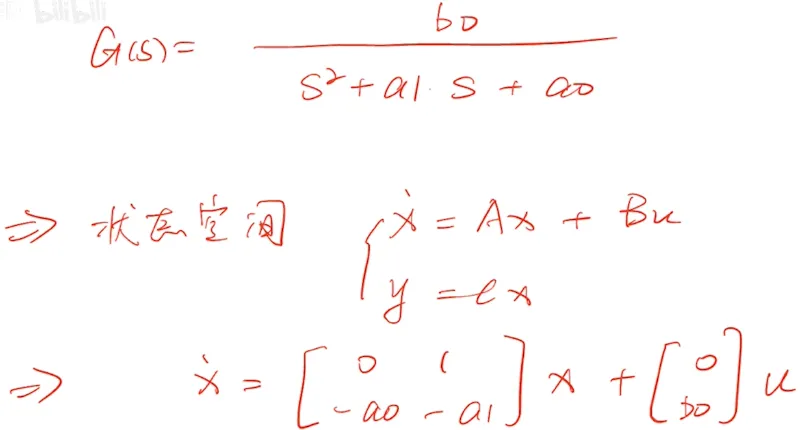
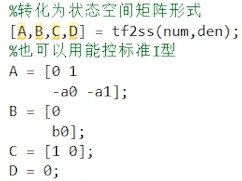
- Write the state equations and the state space.
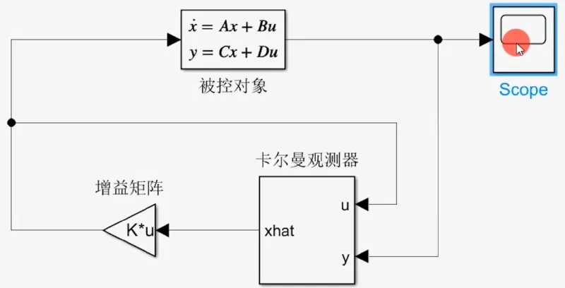
- Build the Simulink simulation system
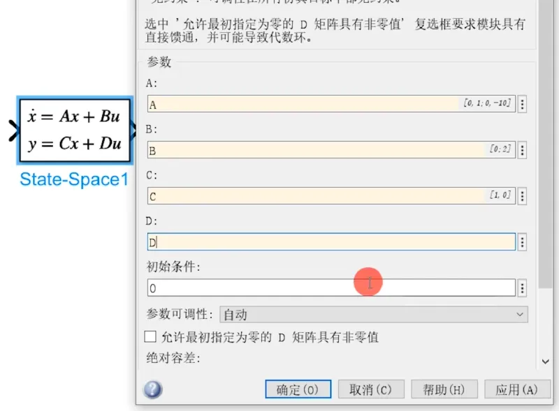
- First set up the state-space equation model
- Then add the Kalman observer
- Complete system structure
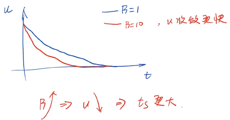
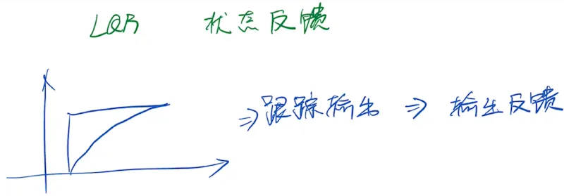
Tuning the QR matrices#
By tuning the Q/R matrices we obtain a new gain matrix , and then do closed-loop state-feedback control.

Example of tuning : is the control input and is time. So when increases, the control input becomes smaller. As a result, the control effort is smaller than before, which leads to a longer response time and slower response.
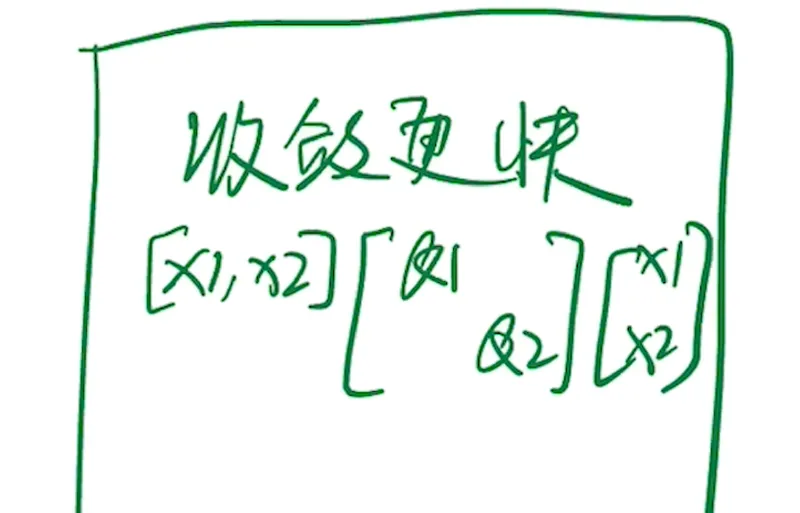
How the QR matrices affect the control system: the QR matrices change the convergence speeds of the corresponding state variables (i.e., how fast they approach 0). If you want a state variable to converge faster and reach zero earlier, increase the weight of that state variable. (For example: to make converge faster, increase ; to make converge faster, increase .)
Tracking the reference input#
- Where do we put the reference input?
-
Suppose we apply a unit step input and want the output to track the reference input. (If you follow only the PID flow and then combine with LQR, you’ll find tracking the reference input cannot be achieved.)
-
Add an integrator before the LQR block. If the control system has an error (difference between actual value and target), it will keep accumulating until the error is eliminated. This solves the issue that pure LQR state feedback can make the output unable to track.
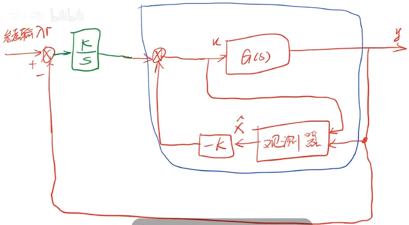
- Why add output feedback additionally: since LQR itself is state feedback, to track output you need output-feedback control. Introducing an integrator can achieve this.
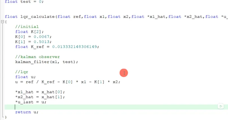
The C program corresponding to LQR in real hardware#
- Variable initialization
- Observer computation
- Feedback: multiply gain matrix by the corresponding state variables
- Obtain the control input