
Tutorial: Perception Stack Setup for an Autonomous UAV
How to connect and configure perception modules in an open-source UAV hardware project.
Preface#
Configuring perception modules is often the most patience-testing part of UAV development. It doesn’t have the clear mathematical derivations of flight-control algorithms, nor the “what you see is what you get” nature of mechanical structures. Instead, it’s more like a long game against software/hardware compatibility, communication protocols, and physical connections. In plain terms, this process doesn’t really involve deep principles or complex derivations—more often, you just need someone to walk you through it once, and then everything clicks.
When building the perception stack for an autonomous UAV, you may bounce back and forth between “the cable isn’t plugged in right” and “the driver isn’t installed correctly.” Three hours ago you might have felt lost staring at scattered aviation connectors, regulator modules, and messy wiring harnesses on the desk; three hours later, when the first crisp frame of point cloud finally starts dancing in RViz, that joy—your heartbeat resonating with the frame rate—makes it all feel worth it.
This article is not a dry parameter manual, but a hands-on review that balances both “mindset” and “moves.” I’ll start from the most basic physical wiring, go through NUC environment setup and ROS driver installation, and end with getting the Mid-360 running FAST-LIO mapping and building an Octomap occupancy grid. I hope this record becomes a future memo for both of us: when facing a jungle of errors, don’t panic—follow the map.
Part 1: Hardware Assembly#
First, let’s learn how each sensor communicates with the main compute device, so we understand where each part sits and how data flows.
Connecting the NUC to the flight controller#
Use the flight-controller cable (double-left-bend 0.15m): connect the USB end to the NUC, and the other end to the flight controller’s Type-C port. This enables communication between the flight controller and the onboard computer. I won’t include a wiring photo here—just pick the correct cable and plug it in.
Connecting the stereo depth camera (Realsense D435i) to the NUC#
Just use a USB to Type-C cable to connect the depth camera to the NUC. But if you’re running VINS-type algorithms, it’s best to use a cable that supports USB 3.0, because other cables/protocols may not provide enough bandwidth for VINS and can cause tracking loss.
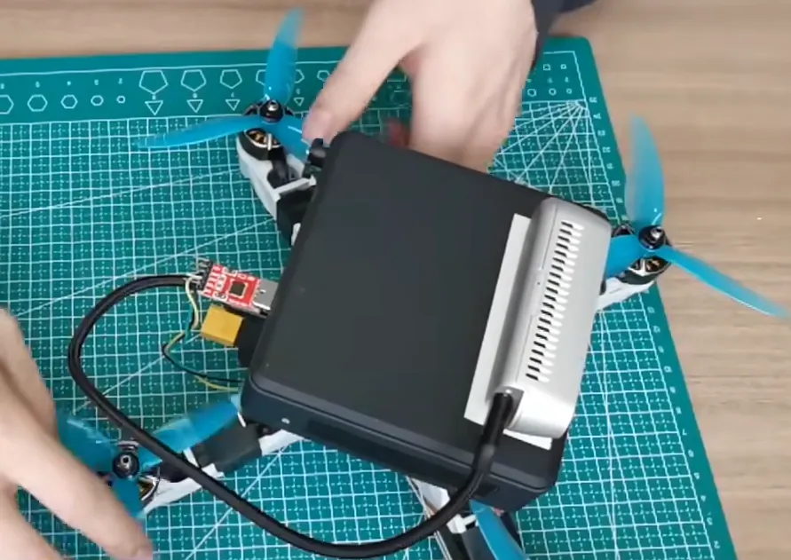
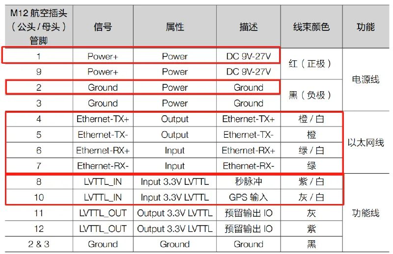
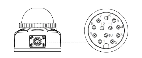
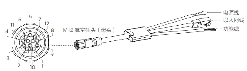
Mid-360 LiDAR power and connecting to the onboard computer#
The LiDAR uses a 12-pin aviation connector. Eight lines are signal lines, four lines are Ethernet lines connected to the onboard computer (NUC). The other four reserved function lines can be used for GPS or other devices (or left unconnected). Two lines are for power; depending on your battery voltage, you can either connect directly to the battery or through a regulator module. If you have the conditions, it’s recommended to modify the aviation connector—this can greatly help with lightweighting and power convenience. There are many tutorials on Bilibili; you can search for them.
Part 2: Onboard Computer (NUC) Setup#
Installing Ubuntu 20.04#
With a brand-new NUC and an empty system, the first thing is installing the OS. To beginners this may sound complicated, but in practice it’s very logical as long as you follow the steps. Don’t be afraid—try it along with the tutorial.
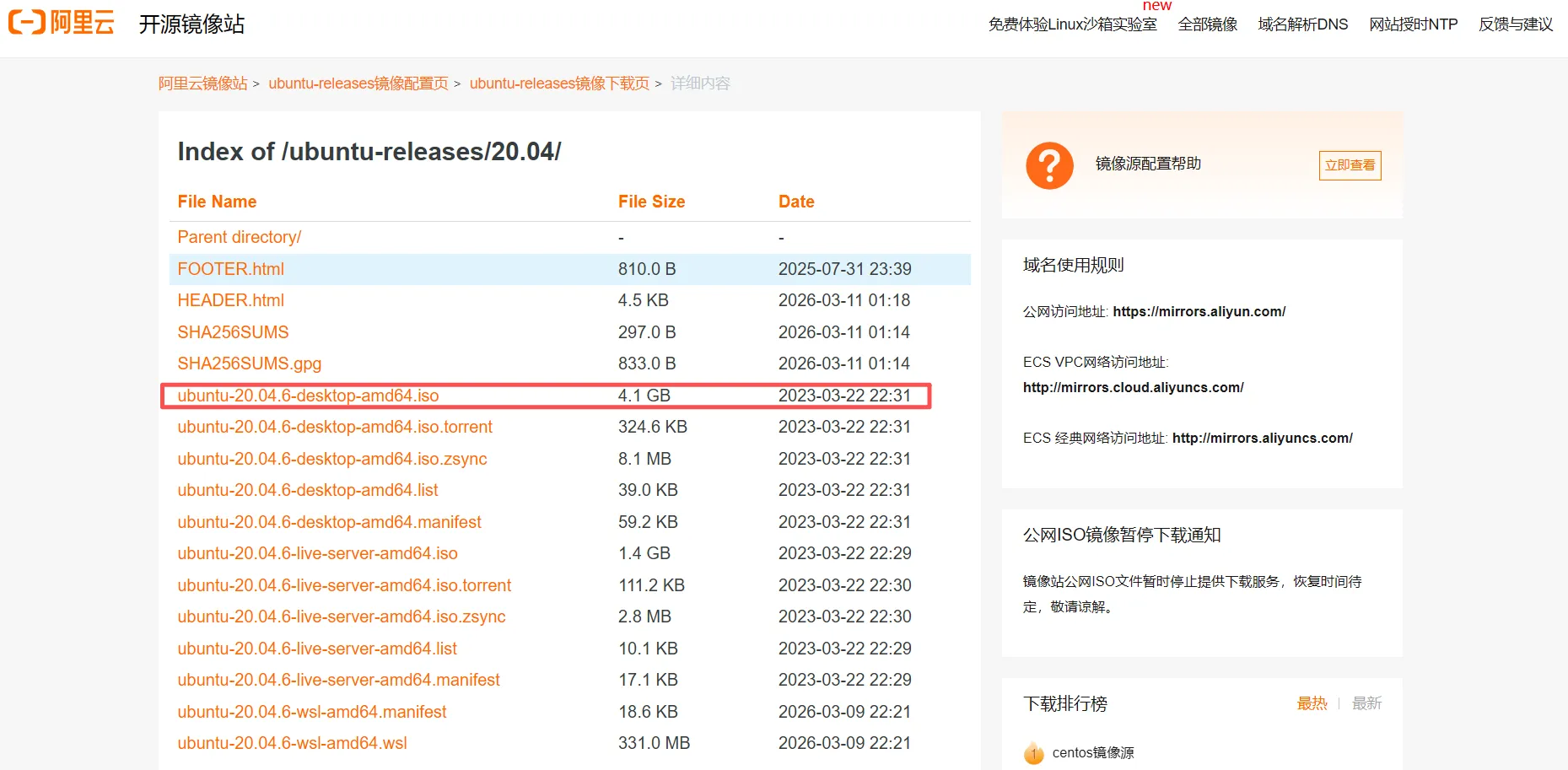
- Download the Ubuntu 20.04 image
You can download the ubuntu-20.04.6-desktop-amd64.iso image from the Alibaba Cloud mirror ↗.
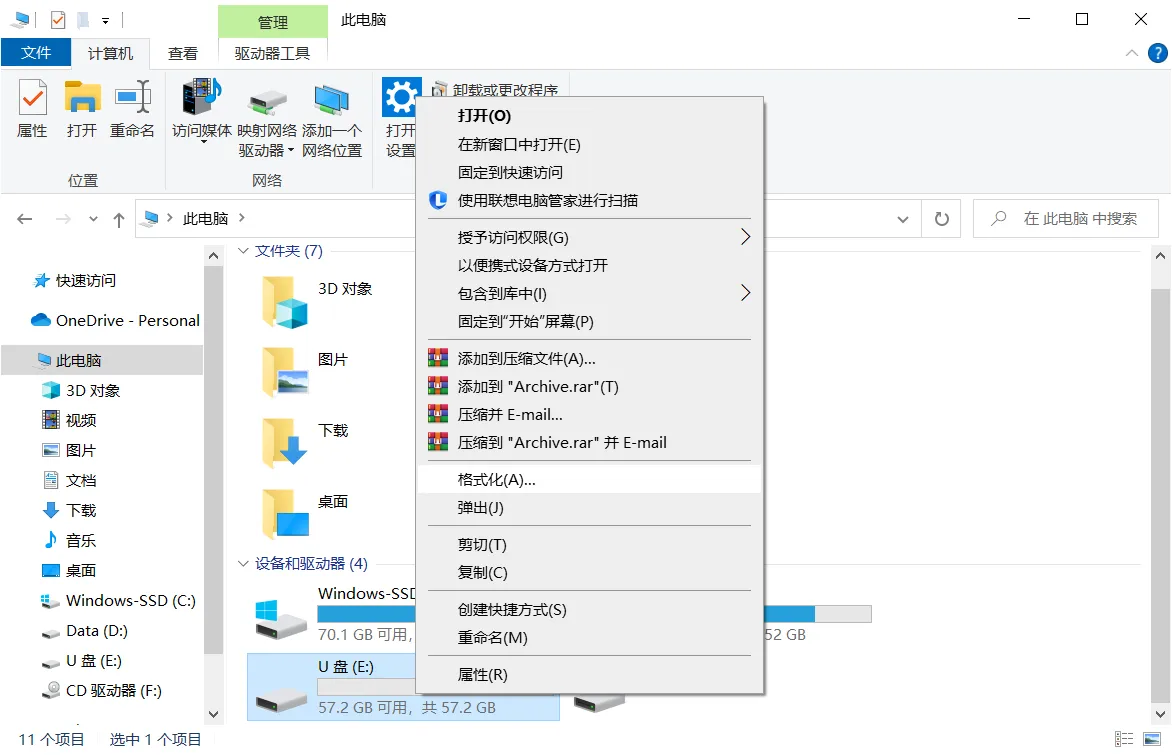
- Flash the image to a USB drive
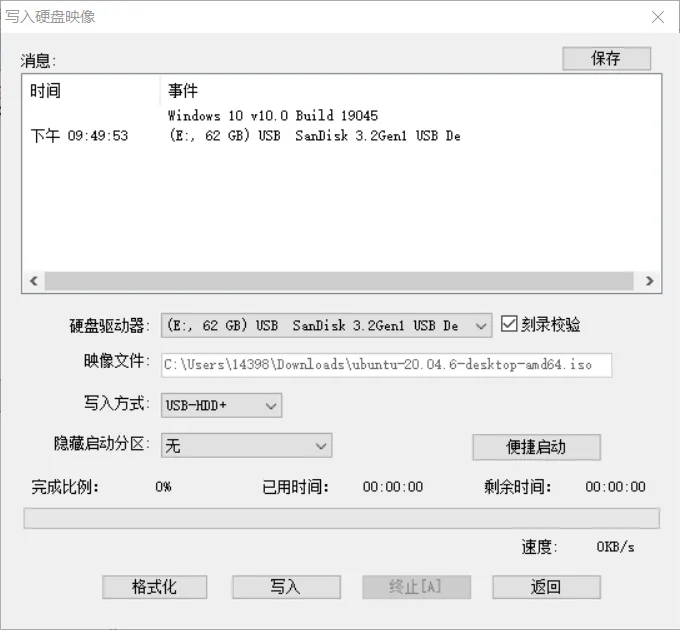
Prepare an empty USB drive (preferably 8GB+). Right-click and format the USB drive on your computer (volume label is optional). The goal is to clear the drive; if it’s brand new, formatting is optional.
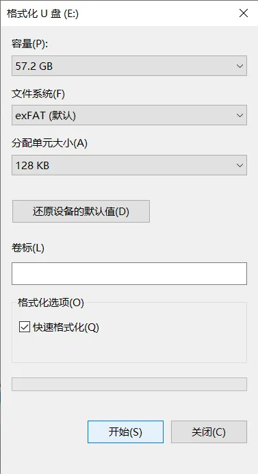
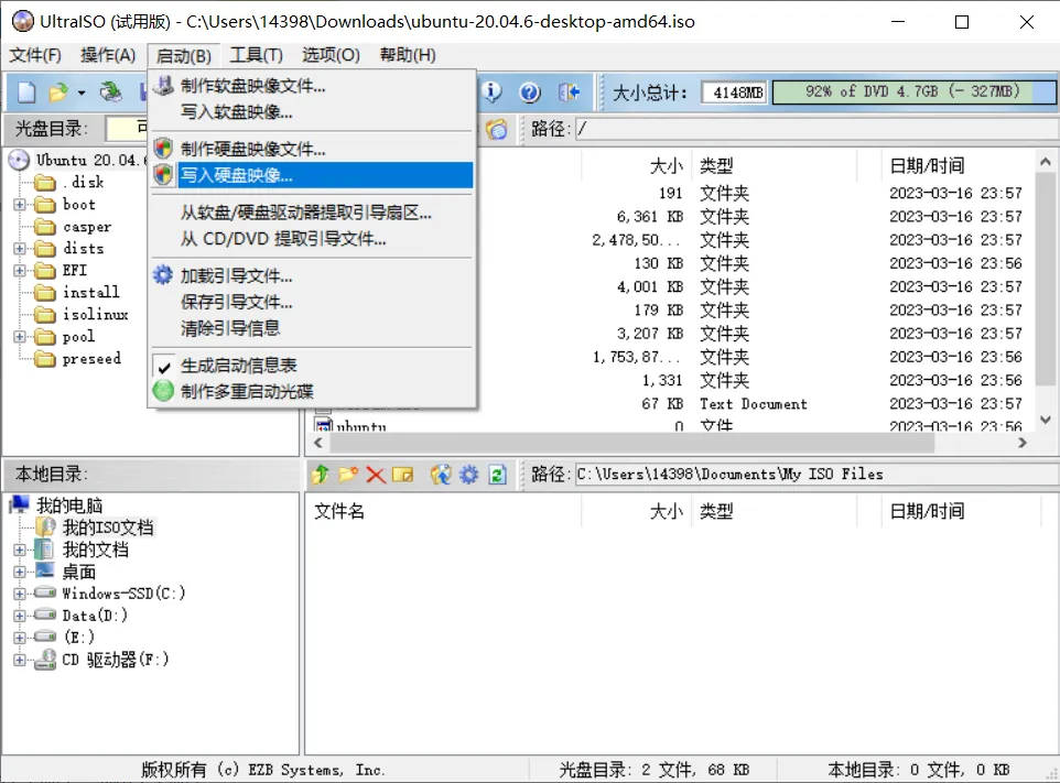
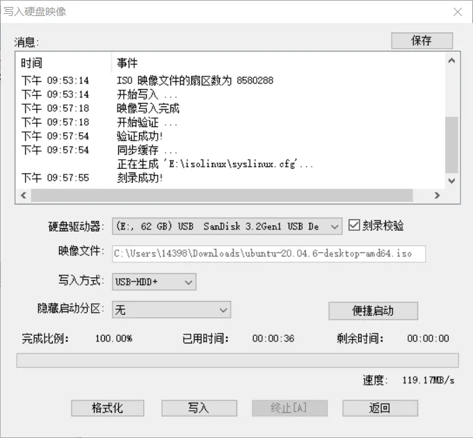
Download UltraISO ↗ and use it to write the downloaded ISO to the USB drive (make sure you select the correct USB drive):
- Install Ubuntu
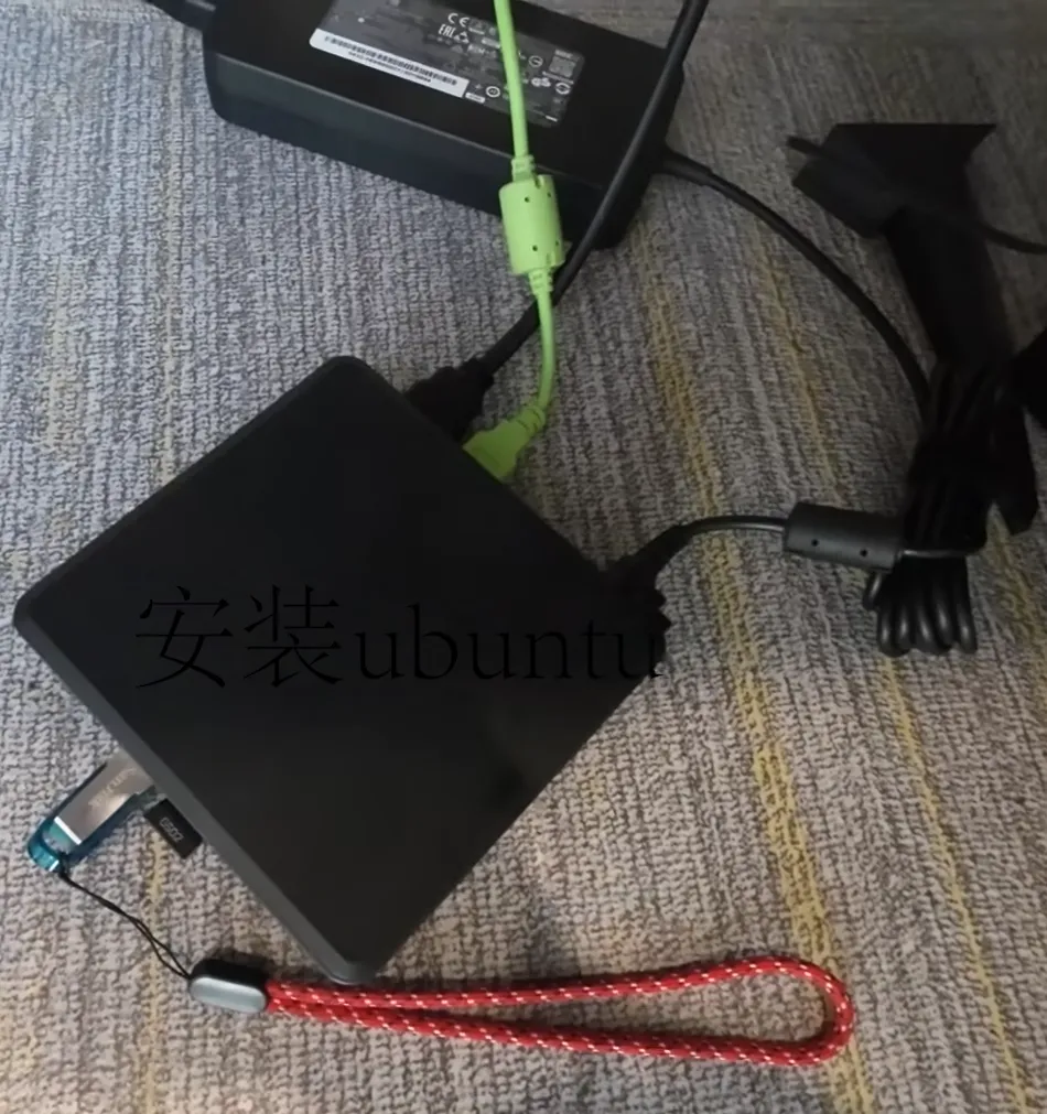
Connect power, the USB drive, mouse and keyboard to the NUC, then press the power button.
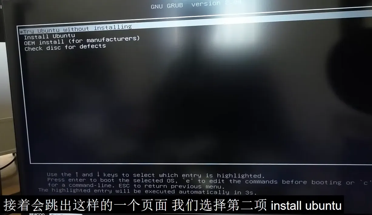
When you see the installer screen, select Install Ubuntu.
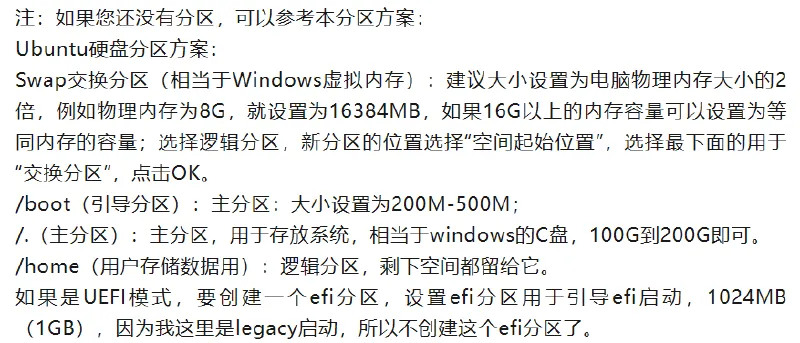
During installation, you can choose Chinese for language; to speed up the process early on, you can temporarily skip network connection and choose normal installation. For a new device, the most critical step is partitioning. If you’re not experienced, you can refer to Ubuntu installation tutorials on Bilibili or follow the partition suggestion shown in the image below. Then follow prompts to choose timezone and set username/password. It’s strongly recommended to enable automatic login—this saves the hassle of typing your password on every boot and is friendlier for later autostart scripts. After everything is set, wait for installation to finish, reboot into the desktop, and you’ll have a fresh Ubuntu machine.
Wi-Fi connection issues#
Ubuntu 20.04 has been out for a long time, and it may soon stop receiving maintenance. It might not recognize the Intel AX211 Wi-Fi card, so right after installation you may find Wi-Fi can’t connect. Don’t panic—there’s always a way. Let’s solve it.
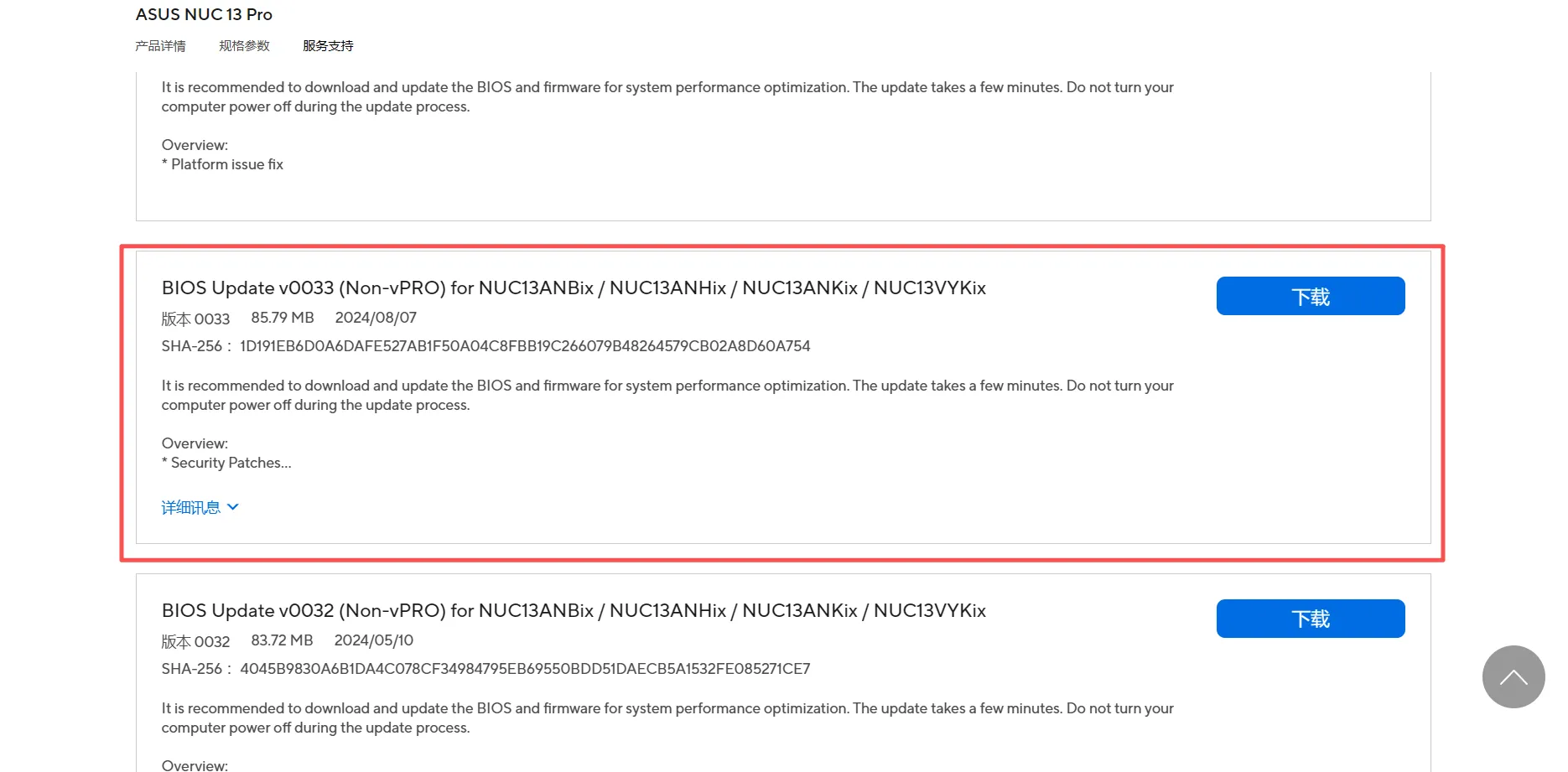
- On another computer with internet access, download the latest NUC13 BIOS 0033 from ASUS NUC ↗. Extract it to a USB drive, unplug the USB drive, then plug it into the NUC.
-
Boot the NUC and press F7 to select the BIOS file on the USB drive. In 0033, choose < Capsue File forCFlash through F7> and press Enter.
-
Reboot and press F2 to enter BIOS, then set
Boot → Secure Bootto Disable. -
Use a USB cable to connect your phone to the NUC. On the phone, enable USB tethering so the phone provides network access to the NUC (without network access, the NUC can’t reach domestic servers and you can’t complete any commands).
-
Then download the driver
backport-iwlwifi-dkmspackage : Ubuntu from this website ↗.
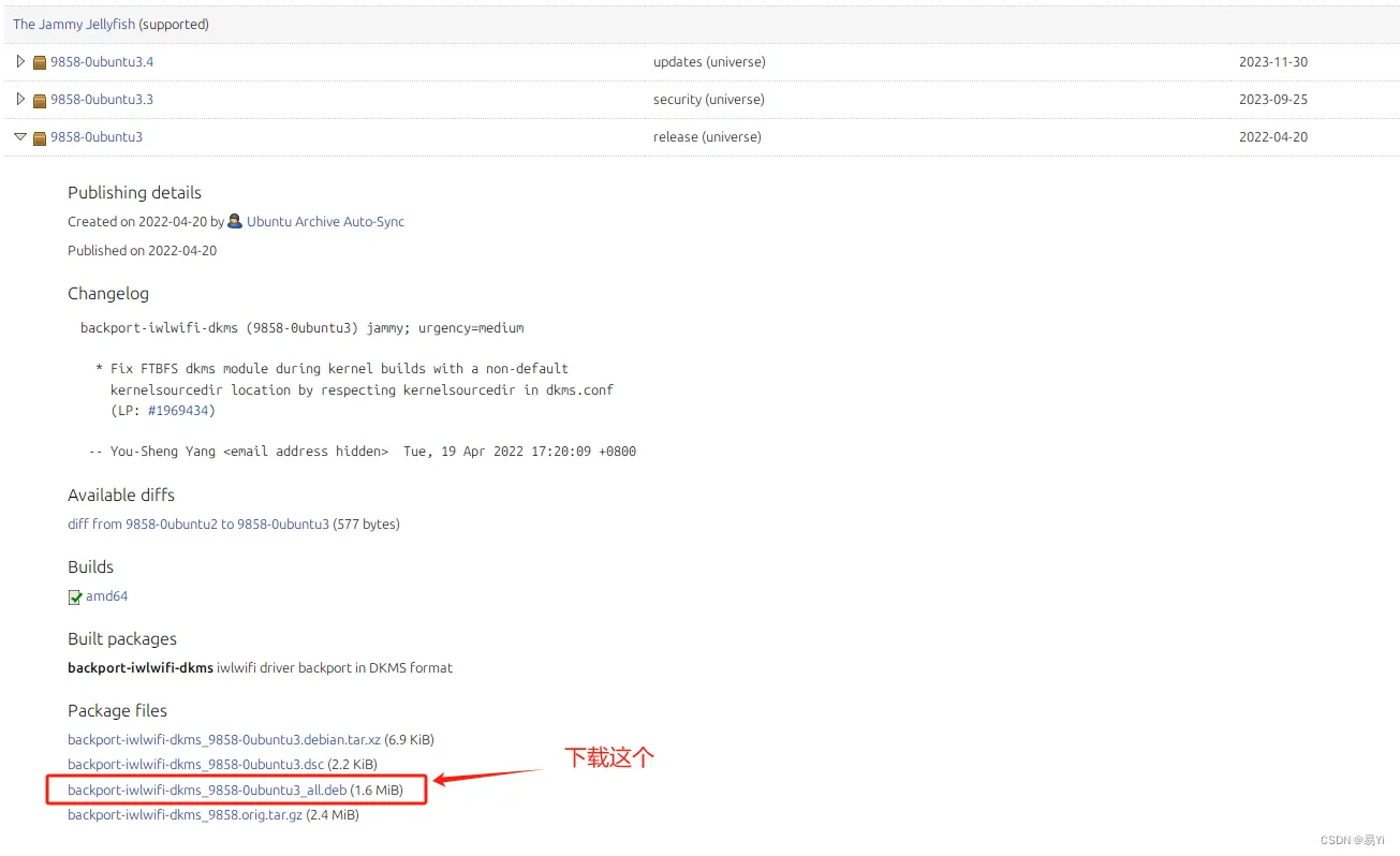
After downloading, install it in the same directory as the file.
sudo dpkg -i backport-iwlwifi-dkms_9858-0ubuntu3_all.debIf you get an error like below during installation:
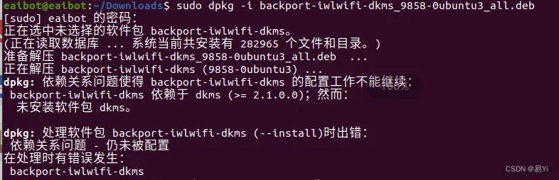
Run the following command, then repeat the steps above and install the driver again.
sudo apt --fix-broken install- Finally, run
sudo apt updateandsudo apt upgradeonce.
Part 3: NUC Environment Setup#
After hardware wiring and OS installation are done, the next step is installing some essential components to make development smoother. This part involves many terminal commands—copy carefully to avoid mistakes.
Install and test ROS#
On Ubuntu 20.04, we need ROS Noetic. The process is basically adding a source, adding a key, updating lists, and then installing the full desktop version. If you’re new to ROS, I recommend following the ROS tutorial in my project ROS Robot Development Learning Base ↗: learn by doing small demos step by step—sharpening the axe doesn’t slow down chopping wood.
Run the following commands in order:
# Add source
sudo sh -c 'echo "deb http://packages.ros.org/ros/ubuntu $(lsb_release -sc) main" > /etc/apt/sources.list.d/ros-latest.list'

# Add key
sudo apt-key adv --keyserver 'hkp://keyserver.ubuntu.com:80' --recv-key C1CF6E31E6BADE8868B172B4F42ED6FBAB17C654

# Install
sudo apt update
sudo apt install ros-noetic-desktop-full

# Set environment variables
echo "source /opt/ros/noetic/setup.bash" >> ~/.bashrc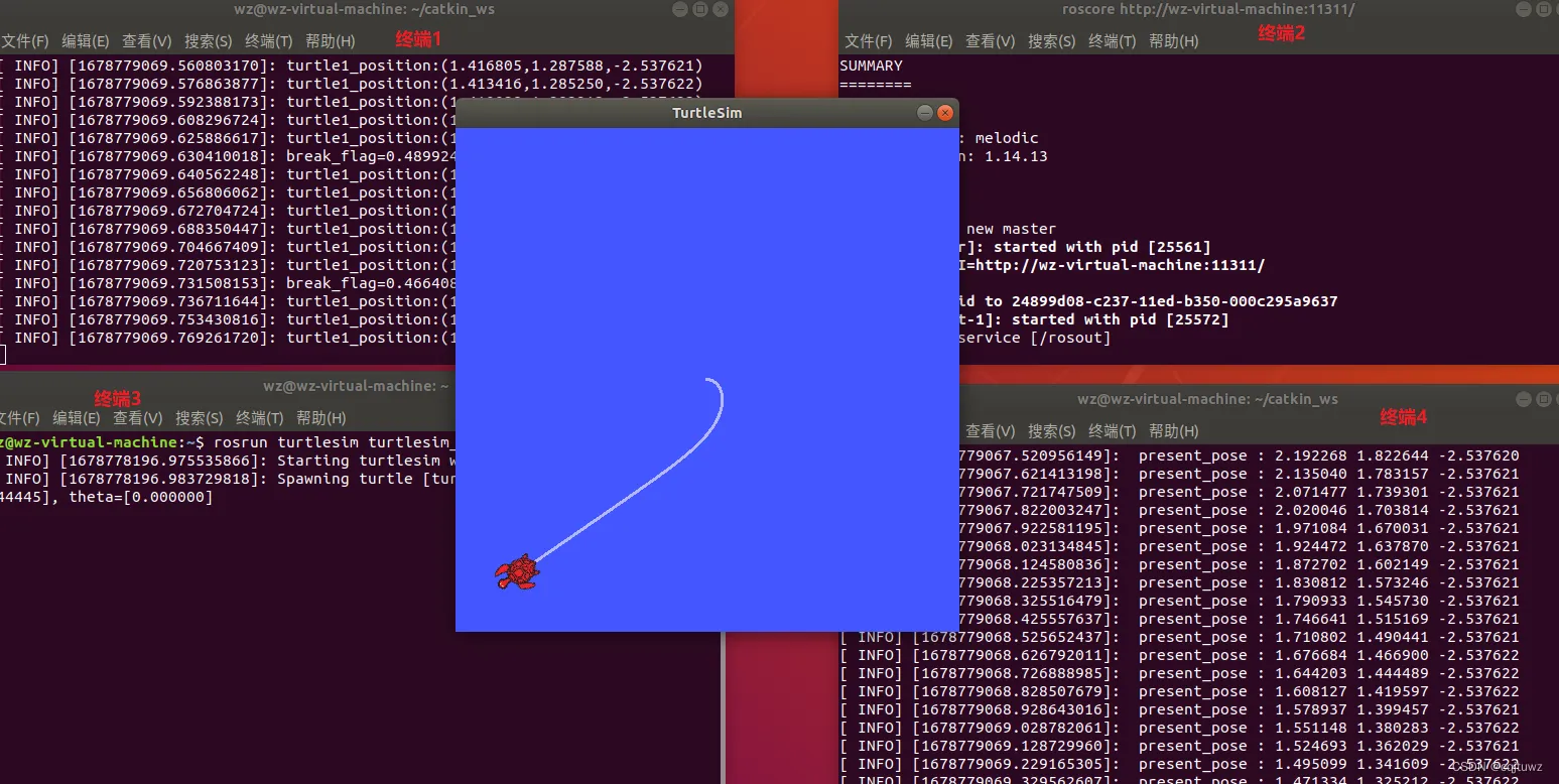
source ~/.bashrcAfter installation, test it with the classic turtlesim demo. Open three terminals and run roscore (start ROS master), rosrun turtlesim turtlesim_node (start the turtle simulation node), and rosrun turtlesim turtle_teleop_key (start keyboard control). If you can move the turtle with arrow keys, congratulations—ROS is installed successfully!
Install Realsense driver and Mavros#
After ROS is installed, we need the NUC to drive the stereo camera and communicate with the flight controller. Here we install the Realsense SDK and the Mavros package.
- Install the Realsense driver
Again, add keys and sources, then install the required dependency packages:
# Add key (if it fails, use the fallback command after ||)
sudo apt-key adv --keyserver keyserver.ubuntu.com --recv-key F6E65AC044F831AC80A06380C8B3A55A6F3EFCDE || sudo apt-key adv --keyserver hkp://keyserver.ubuntu.com:80 --recv-key F6E65AC044F831AC80A06380C8B3A55A6F3EFCDE

# Add repo
sudo add-apt-repository "deb https://librealsense.intel.com/Debian/apt-repo $(lsb_release -cs) main" -u

# Install libraries and tools
sudo apt-get install librealsense2-dkms
sudo apt-get install librealsense2-utils
sudo apt-get install librealsense2-dev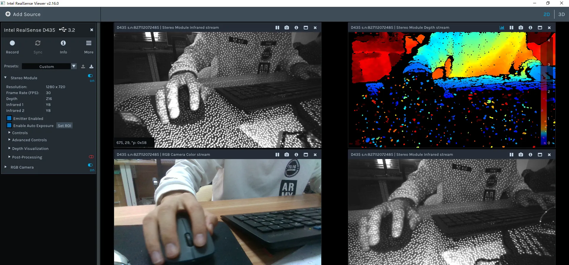
sudo apt-get install librealsense2-dbgAfter installation, run realsense-viewer to start the test tool. Important: check the connection status shown in the top-left of the tool—it must show USB 3.x. If it’s 2.x, check whether your cable supports 3.0 and whether it’s plugged into a blue USB port on the NUC (USB 3.0 cables and ports are usually blue).
- Install Mavros
Mavros is the bridge between ROS and the MAVLink protocol. In the future, we’ll use Mavros to connect communication between the onboard computer and the flight controller.
# These commands may take a while; please be patient
sudo apt-get install ros-noetic-mavros
cd /opt/ros/noetic/lib/mavros
sudo ./install_geographiclib_datasets.shPart 4: Mid-360 LiDAR Setup & FAST-LIO Mapping#
Configure the Mid-360 LiDAR driver#
- Install Livox-SDK2 ↗
This SDK is required to drive the LiDAR and must be installed.
git clone https://github.com/Livox-SDK/Livox-SDK2.git
cd ./Livox-SDK2/
mkdir build
cd build
cmake .. && make -j
sudo make install- Install livox_ros_driver2 ↗
This driver package needs to be cloned into your workspace [work_space]/src/. You can create a dedicated workspace to store LiDAR-related runtime code.
git clone https://github.com/Livox-SDK/livox_ros_driver2.git ws_livox/src/livox_ros_driver2
cd livox_ros_driver2
source /opt/ros/noetic/setup.sh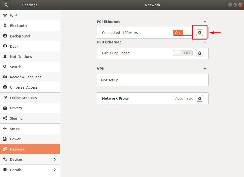
./build.sh ROS1 - Connect the Mid-360 to the NUC
First plug the LiDAR cable into the corresponding ports, then open system settings and follow the steps shown in the images below.
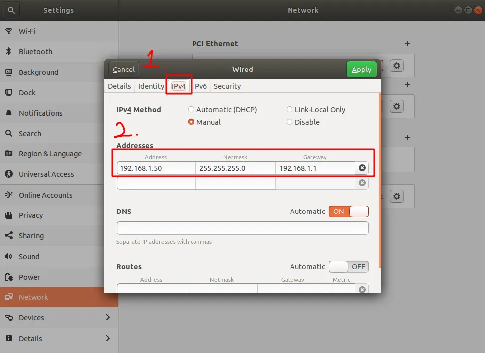
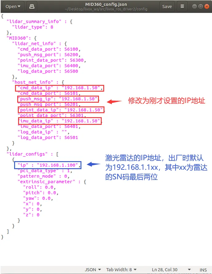
Then modify the corresponding IP address in /src/livox_ros_driver2/config/MID360_config.json.
- Run the launch file to verify installation
In the [work_space] workspace, run the following roslaunch program. If you see point clouds being generated, the LiDAR configuration is successful.
Running FAST-LIO#
The steps above only make the LiDAR driver run, but that alone isn’t very useful. To use the LiDAR as a real perception device for the robot, you’ll want the famous FAST-LIO algorithm—without question a crown jewel in SLAM.
It’s best not to create a new workspace for FAST-LIO. To reduce trouble, I recommend installing it directly in the same workspace used for LiDAR setup. First, download the FAST_LIO source code under [work_space]/src/.
git clone https://github.com/hku-mars/FAST_LIO.git
cd FAST_LIO
git submodule update --init
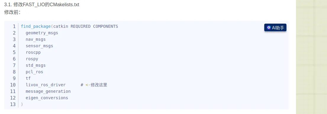
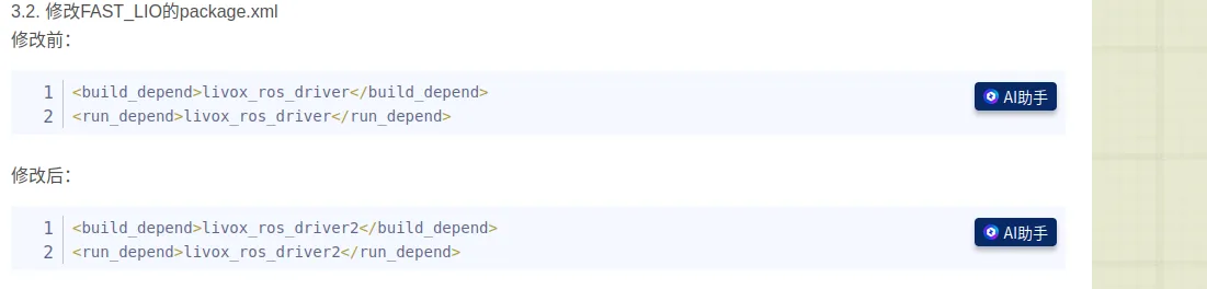
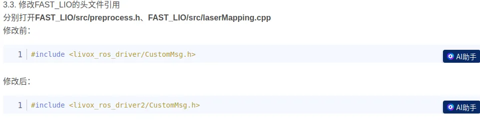
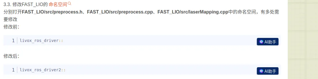
cd ../..Now you hit the first “gotcha”: the FAST_LIO source currently uses livox_ros_driver, but you are actually using livox_ros_driver2. So during CMake compilation you need to change the referenced package according to the tutorial. The specific changes are shown in the images below.
After finishing the changes, you can start compiling. FAST_LIO depends on livox_ros_driver2, so make sure livox_ros_driver2 is built before FAST_LIO, and then build the entire workspace. If livox_ros_driver2 hasn’t been built yet, move FAST_LIO out of the src folder, build livox_ros_driver2, then move FAST_LIO back.
catkin_makeAfter a successful build, run a test. Open two terminals. In terminal 1, run:
source devel/setup.bash
roslaunch livox_ros_driver2 msg_MID360.launchDon’t close this running terminal. In terminal 2, run:
source devel/setup.bash
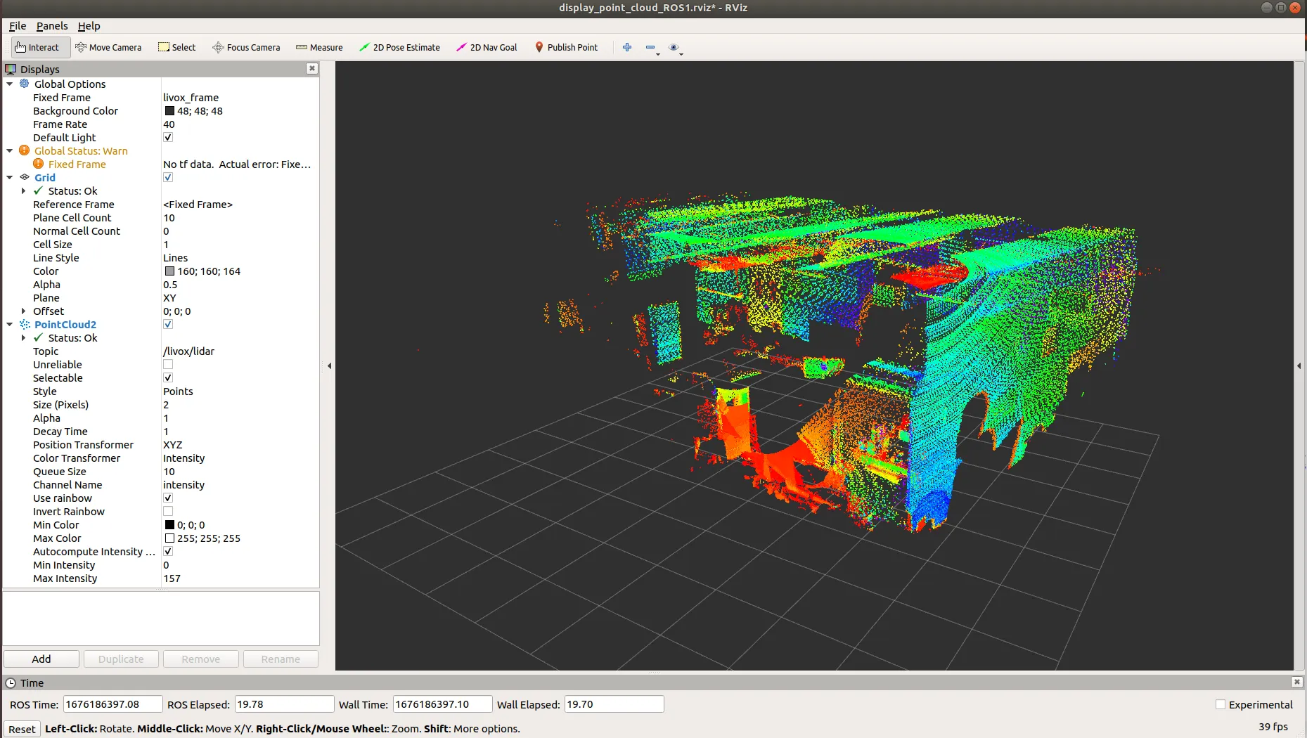
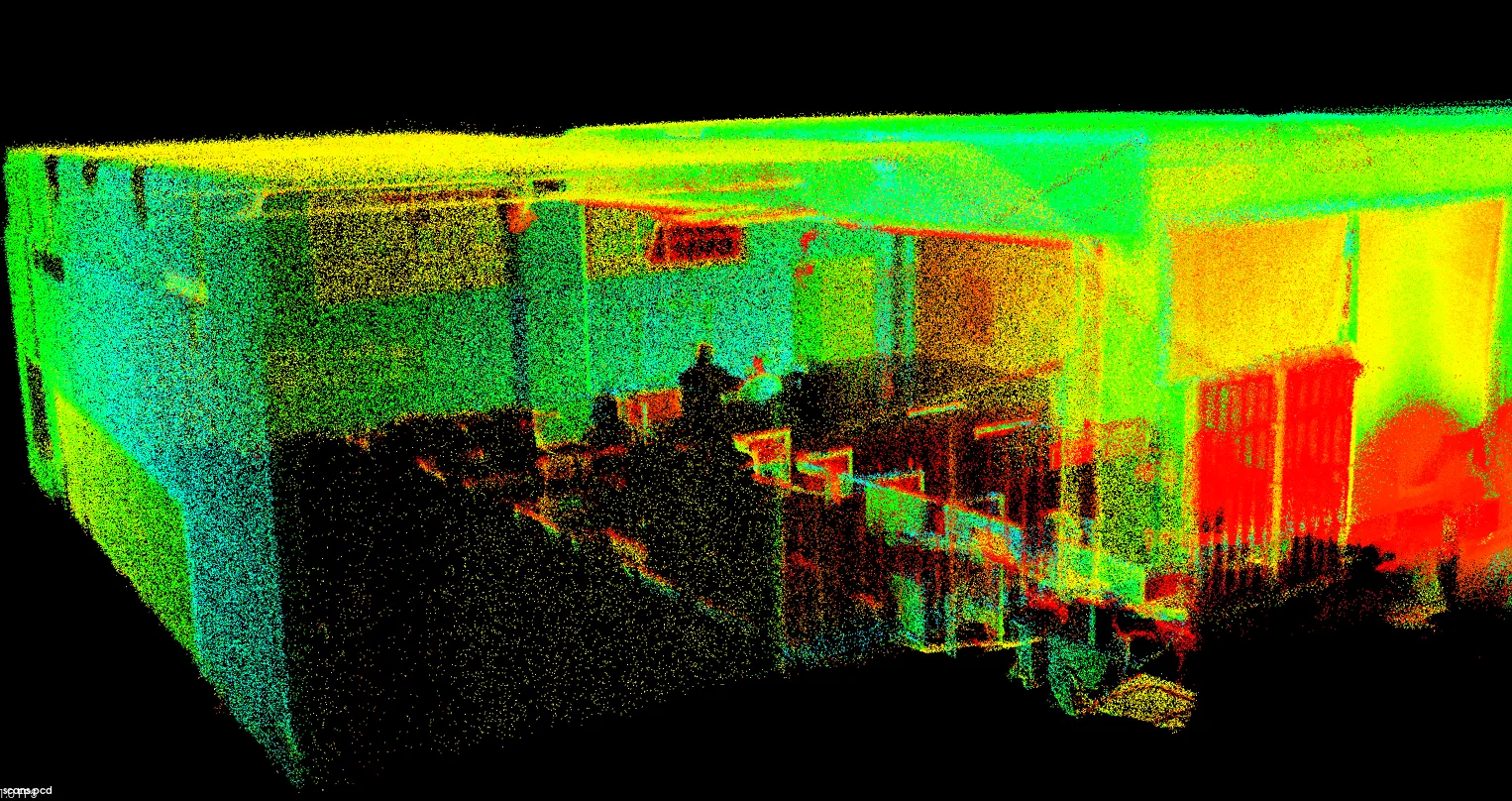
roslaunch fast_lio mapping_mid360.launchIf everything runs successfully, you’ll see a point cloud result like below.
At this point, the LiDAR setup is basically complete. You can build many interesting things on top of these excellent open-source algorithms and truly make your robot move.
Part 5: Octomap Occupancy Mapping#
The point cloud produced by FAST-LIO looks very cool visually, but to path planning algorithms (like A* or JPS), it’s just a set of discrete coordinates without clear boundaries. To enable autonomous obstacle avoidance and navigation, we need to convert these sparse point clouds into a language the machine can understand—an occupancy grid map. Octomap is like Minecraft: via probabilistic updates, it splits space into small cubes with clear states (occupied/free/unknown). This is the foundation for subsequent planning algorithms.
Why build from source?#
Although installing prebuilt packages via apt is convenient, I recommend building Octomap from source for configuration. In real development, we often need to adjust map resolution, sensor max range, or even modify projection logic due to different frame definitions. Prebuilt black boxes don’t provide this flexibility. Also, when building from source, it’s best to manually check and adjust header include names. It’s tedious, but it effectively avoids conflicts with old system libraries.
Startup and the data-flow ensemble#
Below is a curated “takeoff” command sequence. It’s recommended to run them in separate terminals in this order:
- Start sensors
First make sure the LiDAR works properly and you can see raw data in RViz.
cd catkin_livox_ros_driver2
source devel/setup.sh
roslaunch livox_ros_driver2 rviz_MID360.launch- Start the localization algorithm (pose estimation)
This is the core of the system—FAST-LIO will provide high-frequency odometry.
cd catkin_livox_ros_driver2
source devel/setup.bash
roslaunch livox_ros_driver2 msg_MID360.launchKeep the previous terminal running, open a new terminal, and start the core algorithm:
cd catkin_livox_ros_driver2
source devel/setup.bash
roslaunch fast_lio mapping_mid360.launch- Build the occupancy grid map
When localization is stable, the Octomap node begins receiving point clouds and poses and builds an environment model in real time.
cd octomap_mapping_ws
source devel/setup.bash
roslaunch octomap_server octomap_mapping.launch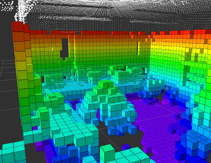
Conclusion#
At this point, we’ve completed the entire workflow—from wiring in the physical world, to installing drivers at the system layer, to building point clouds and occupancy grid maps in the digital world.
Compared with learning research theory, the charm of engineering practice is that it will never be as smooth as a tutorial suggests. In future debugging, you may run into devices dropping due to insufficient USB power, anxiety when Wi-Fi drivers mysteriously disappear, or getting lost in TF frame transformations. But remember: every red Error message is the system trying to tell you its true state. Every time you solve a problem is an upgrade in your understanding of the robot’s underlying logic.
People often say: read more error logs, look up docs more times, accumulate more—be a long-term thinker, and one day it will all connect. I hope this hands-on record becomes your final pre-flight checklist. May your UAV perceive accurately and fly steadily.